Mazda MX-5 Miata banner

Heated Rear Window Wiring Blue Plug To White Fitting?

1 reading
11K views 10 replies 5 participants last post by  Nigsy  
#1 ·
I am trying to wire the rear heated screen up on my mk1 mx5 but seem to have all the wrong parts

My dashboard has the white female plug which even has a couple of wires spliced off for a fog light which must have been done when the car was imported?
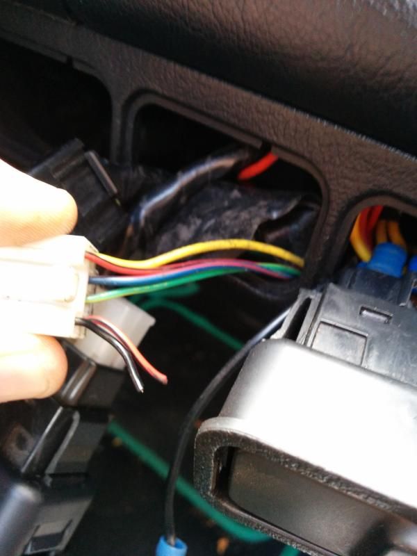
IMG_20140927_120502_zpsb0hjv2kl.jpg

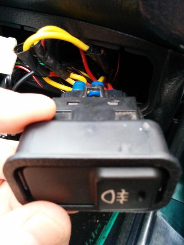
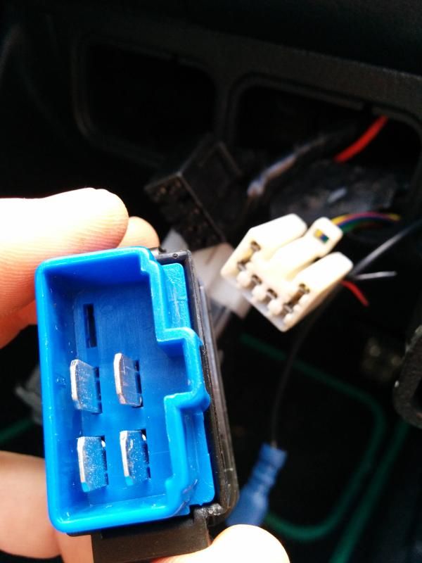
Here is the blue plug I have at the side of the white

Does anybody know which coloured wires should go to which spade on the blue switch?
IMG_20140927_120518_zps9klerhf6.jpg

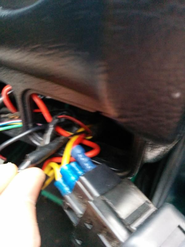
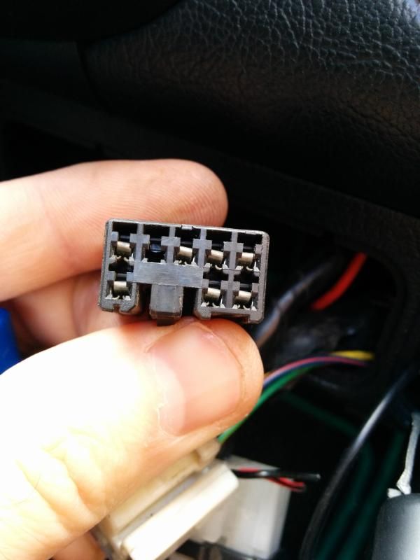
I presume this is for a dimmer switch?
IMG_20140927_120530_zpsnposz1yq.jpg

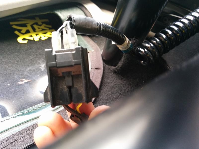
And at the other end the hardtop had a small black plug but the plug on the parcel shelf is a large one

I have this cable now connected up but is this the right order? the two top wires are bridged according to my multimeter and the bottom is the live?
IMG_20140927_120657_zpscannuh12.jpg

any help much appreciated

I did do a forum search but most people just buy the correct switch, however the white backed switch is over ÂŁ50!!!
 
#2 ·
The blue plugged switch, the two middle pins are for the HRW, and two outer ones are for the switch illumination.

The white plug;

1 - 2 - 3 - 4

5 - x - x - 6

1 & 2 are for the HRW,

3 & 4 are for the front fogs

5 & 6 are for the illumination

The black plug with seven terminals I believe is for electric mirrors, the dimmer only has three pins, and it would explain why you have the fog/HRW combo plug.

At the other end, there is two earths, so the other cable is live. One earths to the body somewhere , the other goes goes to the HRW light above the fuel gauge. Afraid I don't know which coloured wire does what, hopefully someone else will know. Failing that you should be able to sort it with a multimeter.
 
#3 · (Edited by Moderator)
The wire to the HRW lamp above the fuel gauge is the red/blue in that first pic at the top. The same wire also goes off to the demister relay in the boot and a sense pin in the ECU (to warn it of extra electrical load I guess).

The yellow wire is a ground wire and appears to be the important one as the switch connects that to the HRW lamp and demister relay.

Not sure what the red/black wire above the yellow is. Perhaps it might be power for switch illumination. <edit because stupid> Monkeydust already explained what it was. Doh.
 
#6 ·
Are the 2 cut off wires for the front fog that I don't have?
They should be, but I can't find them on the badly photocopied Japanese drawing I have. Also the snipped off black wire has the Japanese symbol for "red" on this drawing, so something's not quite the same.

Yellow goes to earth? No.3 on the switch
Red blue goes to no.5 on the switch?
What about red/black and green/yellow?
Yellow goes to pin 3. (Looks like it can also go to pin 1.) Blue/Red goes to pin 4.

Red/Black probably goes to pin 5, but I'm not certain. If the switch is illuminated at night then I think its internal bulb will be between pin 5 and pin 3, but I would check that by measuring the resistance from pin 5 to pin 3 before I connected anything to it. The description is a little ambiguous but I take it to mean pin 5 should be connected to the illumination power source for other existing switches, which seems to be the red/black wire.
 
#7 ·
I've just looked at the wiring in my car, different colours going to the white plug... Different model years I suppose.

From the your pic it looks like they have cut one of the fog wires (makes sense) and one of the illumination wires (less sense). Can you see where the cut off cables now go?

Are the yellow & blue wire in positions 1 & 2 on the layout below? If so, use you multimeter to check which is the live and that goes to 2 on the diagram Martin posted above, with the other going to 4

1 - 2 - 3 - 4

5 - x - x - 6

The red wire, in position 5 on the white plug, check to see if it is live when you have the lights on. If so happy days connect it to 5 on the blue switch, and just earth 3. If it isn't live, and the illumination live is the cut black wire you'll have to find where it went, or take power from another switch. I'd have thought red = live, black = earth, but I'd still check before crimping/soldering.

The red/black & green/yellow in 4 & 3 on the white plug for the front fogs, if you're not planning to fit front fogs ignore them.
 
#8 ·
here is the fog light - as you can see it lights up

IMG_20140928_175221_zpsyelouyfk.jpg

i think the cut red and blue wires are going into the rear fog switch, so does this mean they are for the light on the fog switch?

IMG_20140928_175228_zpsfcxo9pzw.jpg

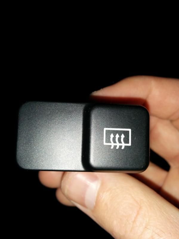
the rear heated screen doesnt light up anyway

IMG_20140928_175439_zpsegcdthbk.jpg

here is a better view of the white connecter

IMG_20140928_175256_zpseogtmma8.jpg

my car is a 96 eunos import btw if that helps at all
 
#9 ·
The cut red and black strip wire I assume is the live for for the front fogs, which is only powered when the lights are on which makes it useful for wiring up a rear fog, it also probably where they got the power to illuminate the rear fog switch. The cut black I think is probably the earth for the illumination, but I'd double check that the red non-cut red with black strip is the live for the illumination, if it is you could just earth it wherever is most convenient.
 
#11 ·
Thanks everyone for the helpful pics, diagrams and info - did this yesterday - using MonkeyDusts instructions and referring to the other pics

Mine had slightly different colours, and my blue HRW switch only had 4 pins (2,3,4,5) but I connected mine up in the following way. (Using MonkeyDusts Pinout and Martin Ys switch Pic)

Plug Pin 1 (which on mine was a faded yellowy purple colour) -> went to Switch Pin 4 (To Relay)

Plug Pin 2 (Red/Blue) was Live -> Switch Pin 2 (To Ignition Live)

Plug Pin 5 (Red Black) went to -> Switch Pin 5 (Illum)

Switch Pin 3 I just earthed behind the dash

For info - I took MonkeyDusts plug pinout to be from the reverse (where the wires go in - this is prob the norm - Its just not 100% clear above

1 - 2 - 3 - 4

5 - x - x - 6

I left the three remaining wires (3,4,6 / Green,Red(ish) & Black(ish) i think) which I'm guessing are for Fog

Onto the boot. Check youve got a mini fuse box near the electrical aerial - with 2 fuses. I tested mine by swapping fuses about and testing with the Electric Aerial - to help confirm which was which and that both fuses were not busted (I then quickly tested the correct fuse slot with a multimeter (think it should have constant 12V)

Then check youve got an LA10 relay behind the rear inner boot panel (inside the boot - reverse of number plate panel)

I also had no Pigtail Y harness wire - going from the 3 pin HRW plug on the rear deck to the rear screen. Strangely I had a homebrew one in the garage (no idea where that came from!!) Would be easy to make - just looks like two wires with an extra live connectors at the HRW deck plug end (ie the live has a little bridge wire coming from the live connector to a second connector) Its clearer here - http://www.mx5nutz.com/forum/index.php?showtopic=132349

The two live connectors go to the top two pins on the rear HRW plug and the black one goes to the bottom pin - connect the other end to the screen.

BINGO! My dash light comes on and I have 12v at the rear screen (When switched on). Thanks again.

.....next sparkly job - why do my washers keep blowing their fuse? ...but not when the wipers are disconnected - hmmmm