Mazda MX-5 Miata banner

Manifold Flange Dimensions For Slide Throttle Project

30 reading
13K views 22 replies 7 participants last post by  George Todd  
#1 · (Edited by Moderator)
Morning everyone,

I've scoured the internet for the dimensions of the BP4W intake manifold flange but haven't come up with anything.

I'm designing a slide throttle, plenum and manifold but don't have access to an engine to strip and measure so progress is coming to a halt.

This particular slide throttle is to be suited for both NA and boosted engines which I don't believe has been done before.

Slide.jpg
Version 1 (now on v3)

If anyone has the dimensions to hand or even a solidworks file I would be grateful. Also is the manifold canted upwards like on the Toyota 2zz engines?

I apologise if this has been asked before (I did search on this forum first!)

Thanks,

George

P.S - it's my first time, be gentle.
 
#4 ·
YOu can buy my old inlet manifold off me for a tenner and then take all the measurements you want ;)
I have a spare in the garage. I'll measure it for you today/tomorrow.
Slot width / height & distance between holes do or do you need stud locations as well?

Sent from my A0001 using Tapatalk
Everything if possible but would happily settle for just the slots!

Thank you so much,

George
 
#7 ·
Interesting project but I don't really see a market for it on an mx5.

If you're doing it for yourself, keep us posted, but if you're doing it to pay your mortgage, I'd have a good think. I presume this is a uni project if you haven't bought a head to do your own measurements, but it's the wrong time in the year....

How are you planning to seal the slide? What idle speed are you targeting?
 
#8 · (Edited by Moderator)
Interesting project but I don't really see a market for it on an mx5.

If you're doing it for yourself, keep us posted, but if you're doing it to pay your mortgage, I'd have a good think. I presume this is a uni project if you haven't bought a head to do your own measurements, but it's the wrong time in the year....

How are you planning to seal the slide? What idle speed are you targeting?
The slide throttle itself would be available stand alone with different port sizes (38mm for most 1.8 engines going up to 44 possibly even 46 for the big boys) I'm not sure wether to machine it to 46 overall and make different size blanks to fit or just machine it in different sizes) the "kit" would come with a manifold to suit the vehicle.

The slide will be inside a sealed box essentially so the only boost leak would be from one side of the throttle to the other but with the tolerances as they are it would be very minimal. Once I've finalised the design a bit more I will do some flow analysis on the computer then do some real world bench testing with the prototype.

The idle speed will be adjustable via a set screw with a sealed dowl.

Edit: forgot to mention it will come with linear slide potentiometers inside for people running aftermarket ECUs and an adapter on the back for those wanting to keep the original rotating style.
 
#10 · (Edited by Moderator)
I like the idea, but how would you balance the ports? Would you rely on the machining tolerances for this?

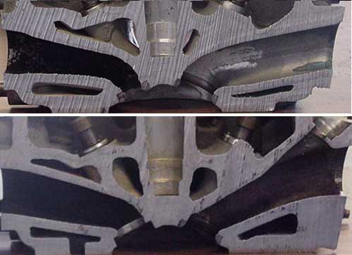
On the "canting" of the ports, this might answer your question (IIRC 94-97 1.8 head above, 99+ 1.8 head below);

141998d1434649947-bp4w-flow-rate-bpheadc
Hopefully a well designed plenum should take care of most of the balancing but if is a problem, I would probably connect all the intake runner via another tube spanning the length of them, similar to most oem Ford manifolds.

That later version head looks like there would be a large restriction on the roof of the port by the valve. Unless I'm mistaken and that improves flow around the valve somehow?

Edit: the intake port I mean. That angular shape not the overall port size.

Thanks for the pictures
 
#11 · (Edited by Moderator)
I like the idea, but how would you balance the ports? Would you rely on the machining tolerances for this?
Hopefully a well designed plenum should take care of most of the balancing but if is a problem, I would probably connect all the intake runner via another tube spanning the length of them, similar to most oem Ford manifolds.
If you're running separate throttles for each cylinder, you'll need some form of adjustment in the linkage to balance them. It's not the ambient pressure you're concerned with, it's the flow to each cylinder (effectively you're after balancing the low pressure behind the throttle of each runner), so the plenum won't help. I presume your Ford example is with a single throttle body if it's on a production manifold?

Have a look at mikuni or keihin motorbike carbs or throttle bodies for what you need to be controlling - they're the best designed individual bodies you'll find (aftermarket car stuff tends to be a bit heath robinson) and they go to great lengths and complexity to include mechanisms to balance the butterflies.
 
#12 · (Edited by Moderator)
I like the idea, but how would you balance the ports? Would you rely on the machining tolerances for this?
Hopefully a well designed plenum should take care of most of the balancing but if is a problem, I would probably connect all the intake runner via another tube spanning the length of them, similar to most oem Ford manifolds.
If you're running separate throttles for each cylinder, you'll need some form of adjustment in the linkage to balance them. It's not the ambient pressure you're concerned with, it's the flow to each cylinder (effectively you're after balancing the low pressure behind the throttle of each runner), so the plenum won't help. I presume your Ford example is with a single throttle body if it's on a production manifold?

Have a look at mikuni or keihin motorbike carbs or throttle bodies for what you need to be controlling - they're the best designed individual bodies you'll find (aftermarket car stuff tends to be a bit heath robinson) and they go to great lengths and complexity to include mechanisms to balance the butterflies.
^^^ This.

I had great fun balancing the ITBs on my old V6 KLMX5 and one of the problems I had was the balance going out of adjustment. Claire (crapengineering) developed them further which I believe cured the problem I had, but unfortunately for me my project had ended before they were available.

If your ITBs are out of balance, the engine will idle like poo. (technical term)

If you're using a single shaft will all butterflies mounted rigidly to it, as long as the quality of machining on the butterflies is good you could probably get away with putting an idle air bleed screw on each runner after the butterfly to get some sort of adjustment. You'd still need to find a way of measuring the total flow rate of each runner (including the bleed), though, as it would be impossible to get it right "by feel".
 
#13 ·
I like the idea, but how would you balance the ports? Would you rely on the machining tolerances for this?
Hopefully a well designed plenum should take care of most of the balancing but if is a problem, I would probably connect all the intake runner via another tube spanning the length of them, similar to most oem Ford manifolds.
If you're running separate throttles for each cylinder, you'll need some form of adjustment in the linkage to balance them. It's not the ambient pressure you're concerned with, it's the flow to each cylinder (effectively you're after balancing the low pressure behind the throttle of each runner), so the plenum won't help. I presume your Ford example is with a single throttle body if it's on a production manifold?

Have a look at mikuni or keihin motorbike carbs or throttle bodies for what you need to be controlling - they're the best designed individual bodies you'll find (aftermarket car stuff tends to be a bit heath robinson) and they go to great lengths and complexity to include mechanisms to balance the butterflies.
^^^ This.

I had great fun balancing the ITBs on my old V6 KLMX5 and one of the problems I had was the balance going out of adjustment. Claire (crapengineering) developed them further which I believe cured the problem I had, but unfortunately for me my project had ended before they were available.

If your ITBs are out of balance, the engine will idle like poo. (technical term)

If you're using a single shaft will all butterflies mounted rigidly to it, as long as the quality of machining on the butterflies is good you could probably get away with putting an idle air bleed screw on each runner after the butterfly to get some sort of adjustment. You'd still need to find a way of measuring the total flow rate of each runner (including the bleed), though, as it would be impossible to get it right "by feel".
It's pretty close to my heart too, having fireblade carbs on the Indy. I ended up making a differential manometer to balance 1 and 2 against each other, 3 and 4 against each other and manometer 1 against manometer 2. They were balanced originally with vac gauges but they don't really have the resolution or accuracy. Now they're within 1/2" of water of each other, the idle and part load pickup is improved massively.

The bleed screw concept is feasible for idle, but because the area change on opening with slide position is non linear, you'll still induce balance issues away from the idle point
 
#14 ·
I like the idea, but how would you balance the ports? Would you rely on the machining tolerances for this?
Hopefully a well designed plenum should take care of most of the balancing but if is a problem, I would probably connect all the intake runner via another tube spanning the length of them, similar to most oem Ford manifolds.
If you're running separate throttles for each cylinder, you'll need some form of adjustment in the linkage to balance them. It's not the ambient pressure you're concerned with, it's the flow to each cylinder (effectively you're after balancing the low pressure behind the throttle of each runner), so the plenum won't help. I presume your Ford example is with a single throttle body if it's on a production manifold?

Have a look at mikuni or keihin motorbike carbs or throttle bodies for what you need to be controlling - they're the best designed individual bodies you'll find (aftermarket car stuff tends to be a bit heath robinson) and they go to great lengths and complexity to include mechanisms to balance the butterflies.
^^^ This.

I had great fun balancing the ITBs on my old V6 KLMX5 and one of the problems I had was the balance going out of adjustment. Claire (crapengineering) developed them further which I believe cured the problem I had, but unfortunately for me my project had ended before they were available.

If your ITBs are out of balance, the engine will idle like poo. (technical term)

If you're using a single shaft will all butterflies mounted rigidly to it, as long as the quality of machining on the butterflies is good you could probably get away with putting an idle air bleed screw on each runner after the butterfly to get some sort of adjustment. You'd still need to find a way of measuring the total flow rate of each runner (including the bleed), though, as it would be impossible to get it right "by feel".
It's pretty close to my heart too, having fireblade carbs on the Indy. I ended up making a differential manometer to balance 1 and 2 against each other, 3 and 4 against each other and manometer 1 against manometer 2. They were balanced originally with vac gauges but they don't really have the resolution or accuracy. Now they're within 1/2" of water of each other, the idle and part load pickup is improved massively.

The bleed screw concept is feasible for idle, but because the area change on opening with slide position is non linear, you'll still induce balance issues away from the idle point
I don't understand why a non linear area change would induce balance issues? Assuming perfectly matched slide ports.
 
#15 · (Edited by Moderator)
I like the idea, but how would you balance the ports? Would you rely on the machining tolerances for this?
Hopefully a well designed plenum should take care of most of the balancing but if is a problem, I would probably connect all the intake runner via another tube spanning the length of them, similar to most oem Ford manifolds.
If you're running separate throttles for each cylinder, you'll need some form of adjustment in the linkage to balance them. It's not the ambient pressure you're concerned with, it's the flow to each cylinder (effectively you're after balancing the low pressure behind the throttle of each runner), so the plenum won't help. I presume your Ford example is with a single throttle body if it's on a production manifold?

Have a look at mikuni or keihin motorbike carbs or throttle bodies for what you need to be controlling - they're the best designed individual bodies you'll find (aftermarket car stuff tends to be a bit heath robinson) and they go to great lengths and complexity to include mechanisms to balance the butterflies.
^^^ This.

I had great fun balancing the ITBs on my old V6 KLMX5 and one of the problems I had was the balance going out of adjustment. Claire (crapengineering) developed them further which I believe cured the problem I had, but unfortunately for me my project had ended before they were available.

If your ITBs are out of balance, the engine will idle like poo. (technical term)

If you're using a single shaft will all butterflies mounted rigidly to it, as long as the quality of machining on the butterflies is good you could probably get away with putting an idle air bleed screw on each runner after the butterfly to get some sort of adjustment. You'd still need to find a way of measuring the total flow rate of each runner (including the bleed), though, as it would be impossible to get it right "by feel".
It's pretty close to my heart too, having fireblade carbs on the Indy. I ended up making a differential manometer to balance 1 and 2 against each other, 3 and 4 against each other and manometer 1 against manometer 2. They were balanced originally with vac gauges but they don't really have the resolution or accuracy. Now they're within 1/2" of water of each other, the idle and part load pickup is improved massively.

The bleed screw concept is feasible for idle, but because the area change on opening with slide position is non linear, you'll still induce balance issues away from the idle point
I don't understand why a non linear area change would induce balance issues? Assuming perfectly matched slide ports.
It's a dead easy design assuming perfectly matched slide ports. Manufacturing tolerances make this a significant design challenge. You'll probably get the holes within a few tens of microns on diameter piece to piece to toolroom standards, within +/-100 microns at reasonable manufacturing cost, but mounting 4 separate slides to a linkage and having them all perfectly timed to 4 other components doesn't happen readily.

If your idle flow is balanced externally to 1 and because of the initial position offset, moving the slide 1 increment makes the flow increase by 0.8,1.3, 1.2 and 1.1, your new flows are 1.8, 2.3, 2.2 and 2.1, ergo, not balanced. Your max flowing body is now flowing 28% more than your least.

ETA - make the ports square and you'll get linear flow with opening...assuming they're all partly cracked at idle, but then keeping idle speed down may become the new challenge
 
#16 ·
1st off, this is a genuine interest! Nice to meet you (again) by the way....

I accept that machining tolerances will always be an issue but assumed 4 holes machined into the single slide would be accurate enough to reduce balancing issues to almost irrelevant? Could the holes not be line machined in their respective housing to ensure 4 perfectly matched ports?
I've seen a lot of older Formula engines, prior to the barrel throttle switch, and none of them had any visible balance adjustment. Admittedly pure power might have been more important.
 
#17 ·
Yes, as you say, match machined as a one off, it's probably passable, but there was talk in the OP of productionising this. Match machining isn't going to make a commercially viable product.

Similar to your comments about race engines, I've never heard anything with barrel throttles idling below about 2500rpm because they're intended for max flow at wide open throttle so sealing isn't a concern. For something street driven, a race engine is a really tiresome prospect.
 
#20 · (Edited by Moderator)
Hi everyone. Here's the latest version of the slide throttle in exploded view.

IMG_8849.jpg

Machining tolerances for critical areas will be within 5 - 10 microns. As for laser cut parts, like the slide, I'm still waiting on a few companies to get back to me.

I'm almost certain that balancing won't be an issue.

As for benefits of the slide throttle design, I'd say it has all the benefits of the barrel type - without the weight and size and it's a neat solution to actuating multiple airways.

when you mention slide throttles everyone's reaction is "oh no, they stick open" because of what happened to the Lister Le Mans cars etc, but if you can get over that one flaw, you have a cheap, simple and elegant solution.

Edit: Outer casing is aluminium, slide is stainless (high polish) they will be separated either by strategically placed PTFE buttons or a thin (0.13mm) glass-fibre reinforced silcicone PTFE sheet.

I will do bench tests to determine which has the lowest friction and sticktion.
 
#22 · (Edited by Moderator)
Four hole true position tolerance on 3 parts and hole diameter within 5-10 microns? More power to you.

Estimated price?

What drove the decision for round holes if you have the machining accuracy to interpolate to your specified tolerances?

I haven't run through the maths, but does the scotch yoke TPS adaptor give you the output you need to mirror a butterfly?
 
#23 ·
Four hole true position tolerance on 3 parts and hole diameter within 5-10 microns? More power to you.

Estimated price?

What drove the decision for round holes if you have the machining accuracy to interpolate to your specified tolerances?

I haven't run through the maths, but does the scotch yoke TPS adaptor give you the output you need to mirror a butterfly?
Not sure of the price just yet!

The reason for round holes and tolerance is because the three pieces will be bored together. Dowel pins will locate the pieces during machining and will be removed after.

I don't think it's an exact match but theres a very close correlation to to a butterfly in terms of open area.